Ok. So–what is the single most important thing in a 2.1 system? It’s the optimum delay. But .. how to know it is right? And–can it be the one discriminator to determine everything else?
Let’s have a look at a bullet proof method to catch 3 tomatoes with one knife: delay, phase and amplitude. How is that supposed to work? Follow the process outlined below using house curve:
- Measure the monitors separately. Safe the outcome. We gonna call this m from now on.
- Measure your sub(s) separately. Safe the outcome. We gonna call this s from now on.
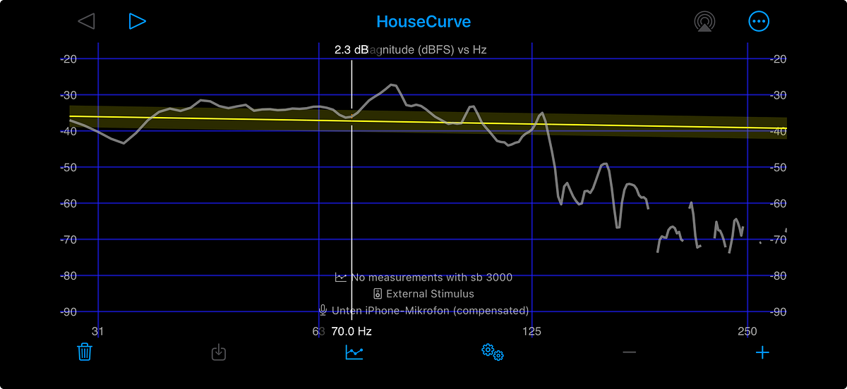
- You now should have 2 measurements that should kind of look like the ones below:


Please note that i already filtered them jointly, so it looks already as good as it can in an untreated room. You do not need to do this round upfront, since the timing does not rely on the signals here. The thing we actually need is the phasing, which is kind of affected as well, but just keep in mind that this is not gonna be a linear process for now. In any case, in sync with the measure above, you also find those phase elements:


This is what we will need to identify the best delay, or at least i shall say, one optimum. There may be more than one, which should be obvious, at least from an acoustic perspective. But this method will get you an optimum, promised.
So as one can see, i marked the position of the intended crossover of 70Hz. You can choose whatever suits your room. You can already see that the slope of the phase, or, the turning speed of the phase, is not identical for both sound devices. If it was, then we could achieve a 100% phase match. This is one of the reasons for me saying that we may yield one optimum, which is not a 100% solution: if both devices were in perfect sync, the left and right phase snapshots above would look identical, with some offset we only then had to find. But we are facing the following issue: once you identified a feasibly correct offset, which is defined by the phase angle of the sub to be ±20–30° max. deviating from the monitor angle. Note that you have all degrees of freedom here: offsetting each side can be a solution, and inverting the phase as well. So eg. one can delay the monitors by about 5ms, which would be SVS’s information on the DSP time, and then maybe see how that works out. The goal is shown on the image below:


Note that you can also do it vice versa–use an isolated measurement of your sub and then measure your monitors on top–it depends a little bit on your setup, and what fits best from a phase turn perspective. In the example above, the monitor side is phase inverted (ø), which gives me mainly congruence specifically between around 45hz and 90hz, which is somewhat the critical integration area. As a rule of thumb, if you want to be more precise, check the isolated measurements around the crossover region (this may also not loook ‘by the book’ for you) and then see at which levels the amplitude will decay to -20db. Below this region, basically no major signal disruption should occur, or, the signal sum is not really relevant any more beyond a conceptual level. Note that those topics are also referred to as low-frequency phase discrimination und group-delay sensitivity respectively.
Some more details:
– The sensitivity is frequency dependant: below 50Hz, a phase difference of <90° is unhearable, at 63–80Hz the threshold is 45–60°, and at around 100Hz it is 30–40°. Above 120Hz, the threshold falls again slightly due to transient phaenomena and overtones.
– This matches the perception: specifically at around 100Hz, the phase alignment is most critical in terms of deviation of the phase slope
– Very important to understand the role of delay and phase inversion here: phase inversion does not alter the phase slope, while for the the delay, you get the following addition to the phase slope at a given frequency f:
ϕ(f)=−360° × f × delay
This means that at 50Hz, you will get an additional phase minus of about -180° in case you are adding 10ms. Note that this is neither good nor bad — depending on your setup, it can be useful to alter the phase.
For a phase inversion, it is basically just shifting the sign. So if you are @75° for 50Hz, you will be @-105° after the phase inversion:
ϕinv=(ϕ+360) mod360°-180°
The heuristics here is to minimize the delta between both phases at and around the crossover region as much as possible. This is limited, as mentioned, by the slope identity: usually each device has a different phase turn speed, which is shown in the slopes above. This, as mentioned, limits the ability to phase align both devices at each frequency. Hence, it must be done by optimization. The first step is to do this via the phase diagram above; once you have something working, you can continue to check the amplitude and somewhat adjust the delay then. But now you are somewhat in the right ballpark when it comes to identifying the delay: per definition, at least around the crossover region, this is what subwoofer integration means.
In the example above, i have around 107° @70Hz for the 8030c side (left image), and around 89° for the SB 3000 side (right image). This is about below 20° and falls into the acceptable region. This aspect relates to a small fraction of ±1ms of runtime difference between the two frequency groups arriving at your ear, which is indistinguishable and hence considered good integration. This is the interpretation of ±20–30° deviation. For convenience, here is the image of the overlayed isolated measurements again, already using quite a good delay value:

Now the next step is to fine tune the amplitude:

One would want to check if slight adjustments of the delay are altering the sum addition between 60 and 120hz, specifically in the crossover region, and then also see if the phase is dramatically changing (should not be the case once you did the first exercise).
The best sum will give you your result, but note that the picture above not much is changing. This is a minor step. One thing to also check here is to disable the phase inversion for a moment and see how deep the dip is you get–the deeper the dip, the better the delay fine adjustment:

Note that the image above compares 4.8ms with 5.3ms. Even though the better amplitude addition (2nd last image) is better with a higher delay, the crossover addition is better with 4.8ms. This should be somewhat obvious: if you consider the different phase slopes for a moment and have a careful look at the above, you will see that a larger delay will a. bring the two phase farther away at exactly the crossover region (70Hz), but closer at regions above, and vice versa. This is a tradeoff you need to take and marks the optimization function here, in essence.
What you can use a discriminator is eg. listening to reverberations in bass tones, bass rich double bass progressions, or also drum and bass, progressive, large drums etc. The result should be as few unwanted resonances as possible, or, the dryest result available.
Now you may ask: how does one know if and where to invert the phase? This is a bit of try and error. The idea is to bring the phase progressions together as good as possible; without touching phase shift functionality in the sub, the only parameters are phase inversion and delay. The phase slope will look different for each parameter changed in isolation, possibly, eg. are frequency additions also affected by room modes etc. so also the phase slop can look slightly different depending on the polarity. You need to try it out and finde the best match between the 2 slopes.
If you have access to a allpass filter, you could change the phase only without changing the timing, but this requires miniDSP and such, as well as is it more costly runtime wise (DSP).